Keyboard backlight
Only the backlit keyboard variants (04X0177, 0C43982) have an LED strip. The
non-backlit 0C44020 has none — on that keyboard the circuit below is simply left
unpopulated and BACKLIGHT_ENABLE = no.
Circuit
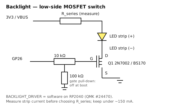
A low-side N-MOSFET switch on GP26. The Pico cannot source the strip’s current directly (GPIO limit ~12 mA; the strip is ~100 mA on comparable ThinkPad arrays).
3V3 ──── R_series ──── LED strip anode (+)
                        LED strip cathode (−) ──── Drain
                                                   Source ──── GND
GP26 ──── 10 kΩ ──── Gate
                     Gate ──── 100 kΩ ──── GND
| Part | Value | Why |
|---|---|---|
| Q1 | 2N7002 (SOT-23) or BS170 (TO-92) | Logic-level VGS(th), turns on fully at 3.3 V |
| Rgate | 10 kΩ | Limits the gate-charge current spike on each PWM edge |
| Rpd | 100 kΩ gate → GND | Holds the gate LOW while the Pico boots and GP26 is high-Z: the backlight does not flash at power-on |
| Rseries | 100 Ω to start — set by measurement | The strip has its own internal resistors on most ThinkPads; measure before trusting any value |
| Supply | 3V3 from the Pico | If the strip is dim at 3.3 V, move the anode to VBUS (5 V) and re-measure current |
Measure before you trust it
- Identify the backlight anode/cathode pins on the keyboard FPC (Phase 1).
- With the MOSFET not fitted, put a multimeter in series and apply 3.3 V through 100 Ω.
- Note the current. Expect tens of mA; delingren measured ~5.6 mA per LED × 18 LEDs ≈ 100 mA on a 04Y0819 with no series resistor.
- If it is under ~20 mA and visibly dim, reduce Rseries or move to 5 V. If it is over ~150 mA, raise Rseries. The USB budget is 500 mA total; keep the backlight under a third of that.
- Record the final values in this file.
QMK driver selection
This is where the earlier plan was wrong.
| Driver | What it is | RP2040? |
|---|---|---|
pwm |
Hardware PWM via ChibiOS PWMD |
Fails to compile on RP2040 — QMK #24470: unknown type name 'PWMConfig', undeclared PWMD4 |
timer |
Interrupt-driven pin toggling | Documented for AVR and STM32; not the RP2040 workaround |
software |
PWM emulated in the main loop | Works on RP2040 — the workaround recorded in #24470 |
custom |
You write it | Unnecessary here |
So: BACKLIGHT_DRIVER = software. The cost is some flicker sensitivity if the scan loop
stalls; at our ~350 µs scan this is invisible. If a later QMK release fixes RP2040 pwm,
switch and record it in CHANGELOG.md.
Reference: QMK backlight docs.
Configuration
/* config.h */
#define BACKLIGHT_PIN     GP26
#define BACKLIGHT_LEVELS  5
/* no BACKLIGHT_BREATHING — unsupported by the software driver */
# rules.mk
BACKLIGHT_ENABLE = yes
BACKLIGHT_DRIVER = software
FN + F11 (CK_BKLT) steps through the five levels. No breathing: backlight_software.c
refuses BACKLIGHT_BREATHING at compile time, so it is not defined.
Troubleshooting
| Symptom | Cause |
|---|---|
| Always off | Gate/drain/source mixed up (TO-92 pinout varies by manufacturer — check the datasheet, not the package shape) |
| Always on, even before firmware | Missing 100 kΩ pull-down |
| On but no dimming | Driver is not software, or BACKLIGHT_LEVELS is 1 |
| Dim | Rseries too high for 3.3 V — measure, then consider 5 V |