Mechanical integration
How every part fits inside the closed assembly. Numbers marked measured are filled in from caliper measurements of the real X240 top section (issue #44); until then they are design targets.
Vertical stack (bottom to top)
| Layer | Height | Notes |
|---|---|---|
| Case floor (printed) / base cover (E1) | 2.5 mm | PETG wall; E1 is ~1.2 mm ABS |
| Standoff under the board | 6.0 mm | M2 brass or adhesive |
| Board (stripboard or PCB) | 1.6 mm | |
| Tallest component above the board | 5.0 mm | ZIF connector body on Rev A breakouts ≈ 5 mm; socketed Pico ≈ 8.5 mm on 2 × 20 headers — the Pico is the tallest item |
| Clearance to the deck’s underside | ≥ 2.0 mm | deck has ribs and the keyboard’s own backplate |
| Internal height needed | ≈ 18 mm | matches internal_h = 18.0 in bottom_case.scad |
If the Pico’s height is the problem, mount it on low-profile (4.3 mm) headers or solder it directly to the Rev B board (drops ~4 mm).
Plan view
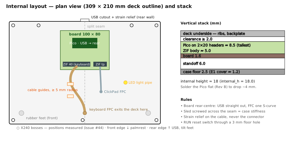
            309 mm
 ┌──────────────────────────────────────────────┐  ← rear edge: USB exit, tilt feet
 │  ○                ○                ○          │  ← rear bosses (measured)
 │                                               │
 │   ┌───────────────────────┐                  │
 │   │ board 100 × 80        │  ← PICO at rear  │
 │   │ [ZIF 40] [ZIF tp]     │     edge, USB    │
 │   └───────────────────────┘     facing out   │
 │         ║ FFC 150 mm, S-curve                │  210 mm
 │         ║ ≥5 mm radius                       │
 │  ○      ╨        ○ keyboard FPC exit   ○     │  ← front-centre: the keyboard's cable exits the deck here
 │                      ClickPad FPC exit        │
 └──────────────────────────────────────────────┘
            front edge: rubber feet recesses
- The board sits rear-centre so the Pico’s USB faces the rear wall and the FFC from the front-centre keyboard exit runs straight back with one gentle S-curve.
- The ClickPad’s short FPC reaches the board’s front edge directly; no extension needed.
- The TrackPoint needs no routing — it rides the ClickPad’s cable.
Cable routing rules
- Keyboard FFC: 150 mm extension, ≥ 5 mm bend radius everywhere, two printed guides (or taped loops) so it cannot migrate into the dovetail seam.
- Never let an FFC edge rest on a screw head or a cut rib — that is where cracks start.
- Tape the extension to the floor at one point only, so thermal movement has somewhere to go.
Screw and boss plan
- Case-to-deck: the X240’s own boss positions (8, measured) with M2 screws into heat-set inserts (printed) or the original threads (E1).
- Board-to-case: 4 × M2 through the sled into case bosses; on E1, 3 × M2 into original mainboard standoffs.
- Sled across the seam: 2 × M2 per half — the sled is the structural bridge.
Connector access
- USB: the Pico’s Micro-USB (or the USB-C breakout) is centred in the rear cutout with 0.5 mm clearance. The strain-relief bezel snaps into the same cutout.
- Reset: the Pico’s
RUNpad goes to a tactile switch reachable through a 3 mm hole in the floor — so the bootloader is reachable without opening the case (BOOTSEL + reset). - LED: the light pipe aperture is beside the touchpad; the pipe presses into the floor aperture and meets the LED on the board’s front edge.
Service access
Remove the deck screws, lift the deck, unlatch two ZIF tabs, and the board comes out on its sled. No glue anywhere in the printed route; in E4 (wood) only the frame is glued.
Gasket
1 mm self-adhesive foam on the printed ledge (1.2 mm deep, 2 mm wide) around the full perimeter, including across the seam. It compresses 0.2 mm when the deck is screwed down — enough to keep dust out and the two halves acoustically dead.