Wiring the Raspberry Pi
Read System overview first. The Pi and the printer talk over the network; the USB cable described at the end is optional.
Mains
The printer PSU is mains powered. Never open the printer base with the power cord connected. Nothing in triaina requires touching mains wiring.
Network connection
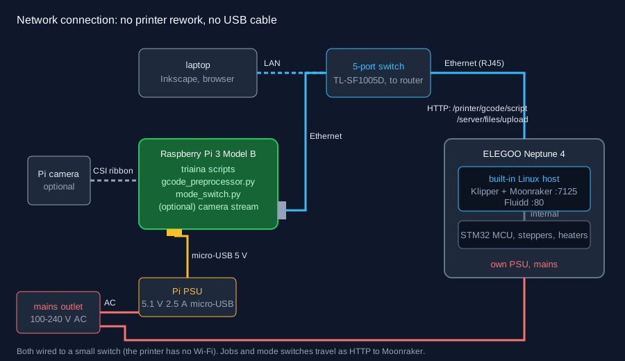
Connections
| # | From | To | Cable | Notes |
|---|---|---|---|---|
| 1 | Wall outlet | Pi PSU | Mains plug | Official 5.1 V 2.5 A unit |
| 2 | Pi PSU | Pi micro-USB power port (bottom edge, next to HDMI) | Captive micro-USB | Do not power the Pi from the printer's USB |
| 3 | Router LAN port | Switch | Cat5e or better | Skip the switch if the router has two free ports next to the printer |
| 4 | Pi Ethernet jack | Switch | Cat5e or better | Or the Pi's Wi-Fi (configured in Raspberry Pi Imager) |
| 5 | Printer RJ45 port | Switch | Cat5e or better | The printer has no built-in Wi-Fi; see below. Note its address or .local name |
| 6 | Pi CSI connector | Camera Module | 15-pin ribbon, contacts toward the HDMI port | Optional |
| 7 | Wall outlet | Printer PSU | Printer's mains cord | Check the 115/230 V switch if your unit has one |
| 8 | Wall outlet | Switch power adapter | Supplied 5 V or 9 V adapter |
Why a switch. The printer is wired-only (an RJ45 port, no built-in Wi-Fi, per Obico's Neptune 4 Pro guide; the Neptune 4 uses the same board), and the Pi is most reliable wired too. A small unmanaged switch next to the printer needs one cable back to the router instead of two. 10/100 is plenty: the Pi 3's Ethernet is 100 Mbit and the traffic is G-code uploads and a status poll once a second. See Parts.
Printer on Wi-Fi instead. Possible with a USB Wi-Fi dongle whose driver the printer's Linux image includes (Obico reports the TP-Link TL-WN725N working), set up over a wired connection first. Wired is simpler and does not drop.
Bring-up order
- Flash Raspberry Pi OS Lite (64-bit) with Raspberry Pi Imager; set host
name
triaina, user, Wi-Fi and SSH in the Imager settings. - Connect the switch (3, 8), then the Pi (4) and the printer (5).
- Power the Pi (1-2). It appears as
triaina.localafter about a minute. - Power the printer (7). Read its IP address on its screen (network
settings) or in your router's client list. Its host name is
mkspi(the board is an MKS-PI), somkspi.localmay also work; the IP always does. A DHCP reservation in the router keeps the address from changing. -
From the Pi, check you can reach Moonraker:
curl -s http://mkspi.local:7125/server/info | head -c 300Replace
mkspi.localwith your printer's name or address. 6. Continue with Raspberry Pi setup.
Optional: USB-C console cable
The printer's USB-C port is the built-in host's serial console. It is useful
when the printer drops off the network: from the Pi you can log in, check
ip addr and restart services. It carries no print jobs.
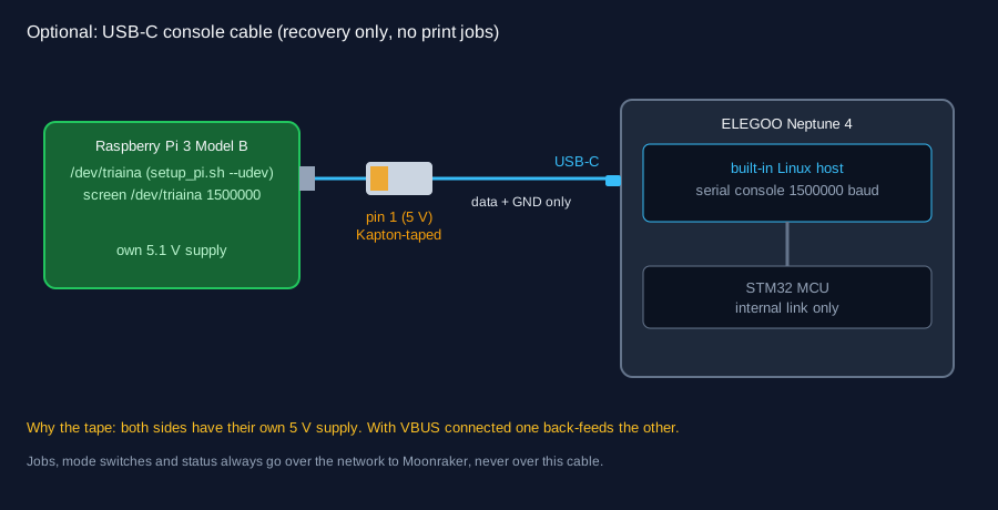
| # | From | To | Cable | Notes |
|---|---|---|---|---|
| 1 | Pi USB-A (any) | Printer USB-C | USB-A to USB-C, pin 1 taped | Data and GND only |
Then on the Pi:
scripts/setup_pi.sh --udev          # binds the console bridge to /dev/triaina
screen /dev/triaina 1500000         # log in; Ctrl-A K to quit
Default login on OpenNept4une images is mks / makerbase; stock ELEGOO
images differ by firmware version.
Blocking 5 V on the console cable
Both boards have their own 5 V supply. With VBUS connected, whichever supply is higher pushes current into the other board. Symptoms range from the printer's board staying half-powered with the printer off, to Pi undervoltage warnings, to a damaged regulator.
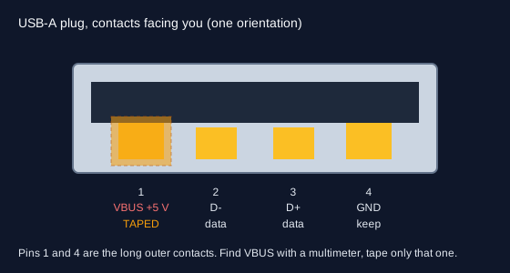
- Unplug the cable from both ends.
- Find pin 1. Pins 1 (VBUS) and 4 (GND) are the two longer outer contacts; which side is which depends on how you hold the plug, so measure: plug the cable's printer end into the powered-on printer, leave the Pi end free, and put a multimeter (DC volts) between an outer contact and the metal shell. The contact that reads about 5 V is pin 1. If the port reads 0 V on both, the printer does not supply 5 V on that port and the tape is still cheap insurance against the Pi feeding it.
- Cut a strip of Kapton tape about 2 mm wide and 10 mm long. Lay it over pin 1 only, fold the end over the tip of the tongue so it cannot peel back on insertion.
- Plug the taped end into the Pi.
- Check: with the printer off and the Pi on, the printer's screen and board LEDs stay dark. If they light up, the tape slipped.
A USB 5 V blocker adapter does the same job without tape. Put it on the Pi end.
Topology B: Pi as Klipper host (experimental)
Unverified, opens the printer
Nobody has confirmed the MCU UART pins on the Neptune 4 ZNP-K1 board for this. Wrong pins or 5 V on a 3.3 V line can destroy the MCU or the Pi. Unplug mains before opening the base. Use Topology A unless you accept that.
The USB-C port cannot be used: it is the built-in host's console. The Pi has to reach the STM32 MCU over a UART instead.
| # | Pi pin | Signal | To |
|---|---|---|---|
| 1 | 8 (GPIO14) | TXD, 3.3 V | MCU UART RX pin (to be identified on your board) |
| 2 | 10 (GPIO15) | RXD, 3.3 V | MCU UART TX pin |
| 3 | 6 | GND | MCU board GND |
Never connect the Pi's 5 V pins (2, 4) to the printer. Each side keeps its own supply.
Steps, in outline:
- Identify a free USART on the STM32 and its pins on the board (schematic, OpenNept4une community, continuity tester). Record board revision and pins.
- Build Klipper MCU firmware for the board's STM32 with that USART as the communication interface; flash it with the microSD method documented by OpenNept4une.
- On the Pi:
dtoverlay=disable-btin/boot/firmware/config.txt(gives the full PL011 UART on/dev/ttyAMA0), disable the serial login console, install Klipper, Moonraker and Fluidd with KIAUH. - Stop the built-in host's Klipper service so it does not fight for the MCU.
-
In the Pi's
printer.cfg:[mcu] serial: /dev/ttyAMA0 baud: 250000 restart_method: commandCopy steppers, probe and bed-mesh sections from the stock
printer.cfg. 6. Add[include klipper_cutter_macros.cfg]as in Klipper macros, and setTRIAINA_HOST=localhost.
If you get this working, open an issue with the board revision and pins so it can move out of experimental.
Checklist
- [ ] Pi on its own 5.1 V supply
- [ ] Pi and printer on the same network, Moonraker reachable from the Pi
- [ ] (console cable only) 5 V pin blocked, verified with the printer off
- [ ] (Topology B only) UART at 3.3 V, GND shared, no 5 V between boards
- [ ] Knife holder mounted, see Mounting the knife